
– 1 –
Dipl. Ing. Yu Bin, Global System Expert E-Mobility, DSM Engineering Materials
Dr. Tamim P. Sidiki, Global Marketing Director Mobility, DSM Engineering Materials Dr. Robert R. Janssen, Principle Scientist, DSM Engineering Materials
Material solutions to increase tank-to-wheel efficiency and life-time reliability of fuel cells vehicles
Materiallösungen zur Steigerung der Effizienz von Tank zu Rad und der
Lebensdauerzuverlässigkeit von Brennstoffzellen
Please keep the footers free from own writings!
Abstract
Material solutions to increase tank-to-wheel efficiency and life-time reliability of fuel cells vehicles
Fuel cell technology is an important contributor to zero emissions in transportation. The fuel cell stack, as the heart of the fuel cell engine, is an electrical chemical device. Due to its working mechanism and working condition, ions which would leach out of the materials used in the fuel cell can cause catastrophic consequences, such as poisoning of the catalyst, clogging of the membrane and decreasing system insulation levels. Such ions can also accelerate the corrosion of the metallic bi-polar plates. Moreover, hydrolytic degradation of the plastic components can result in mechanical deterioration and dimensional creep, which put the system’s robustness and media sealing performance at risk. In this presentation we will present latest results on the impact of such ion leaching and how dedicated material developments can not only lead to the lowest ion leaching, but additionally also achieve high mechanical retention and weld line strength amongst all engineering materials. As a result, the challenging reliability and efficiency requirements of fuel cell operation also over 20,000 hours life-time can be achieved.
Kurzfassung
Materiallösungen zur Steigerung der Effizienz von Tank zu Rad und der
Lebensdauerzuverlässigkeit von Brennstoffzellen
Die Brennstoffzellentechnologie leistet einen wichtigen Beitrag zur Emissionsfreiheit im Verkehr. Der Brennstoffzellenstapel ist als Herzstück des Brennstoffzellenmotors eine elektro-chemische Komponente. Aufgrund des Funktionsmechanismus und ihrer Arbeitsbedingungen können Ionen, die aus den in der Brennstoffzelle verwendeten Materialien herausgelöst werden, katastrophale Folgen haben, wie z. B. eine “Vergiftung” des Katalysators, ein Verstopfen der Membran und eine Reduktion der
Isolationseingenschaften innerhalb des Systems. Solche Ionen können auch die Korrosion der metallischen bipolaren Platten beschleunigen. Darüber hinaus kann eine hydrolysebedingte Beeinträchtigung der Kunststoffkomponenten zu einer mechanischen Verschlechterung und einer Veränderung der Abmessungen führen, wodurch die Robustheit und die Dichtungsleistung des Systems gefährdet werden. In dieser Präsentation werden die neuesten Ergebnisse zu den Auswirkungen einer solchen Ionenauswaschung vorgestellt und wie spezielle Materialentwicklungen nicht nur zu einer der weltweit niedrigsten Ionenauswaschung führen können, sondern auch eine sehr hohe mechanische Retention und Schweißnahtfestigkeit unter allen technischen Materialien erzielen. Dadurch können die anspruchsvollen Zuverlässigkeits- und Effizienzanforderungen des Brennstoffzellenbetriebs auch über eine Lebensdauer von 20.000 Stunden erreicht werden.
Abstract
Fossil energy enabled the Industrial Revolution, but it is also the most negative source of localized air pollution and an emitter of CO2 and other greenhouse gases. According to the World Health Organization (WHO) nine out of 10 people on the planet breath polluted air, killing seven million people each year. The WHO concludes that approximately a quarter of all deaths from heart disease, stroke and lung cancer can be attributed to air pollution. The rise in global average temperatures is attributed to an increase in greenhouse gas emissions, which is why global efforts are being taken to move away from fossil energy and towards more sustainable energy—the end game being renewable power sources.
Among the different sources of greenhouse gases, the emissions from the transport sector, chemical industry and steel industry are major contributors to climate change—for instance about 4% of total annual emissions and around 24% of CO2 emissions are generated from burning fossil fuels in the transport sector. However, the fossil alternatives in transportation—e-fuels, pure battery and fuel cells—all have some limitations, which are a challenge for a broader market acceptance.
In this paper we will focus primarily on hydrogen fuel cell technology and demonstrate major improvements in ionic leaching and hydrolytic resistance of used engineering materials, which directly impact tank-to-wheel efficiency and life-time reliability of the fuel cell stack in operation. Tackling the current drawbacks of fuel cell technology will be an important contribution to increasing market acceptance, hence market penetration.
Hydrogen is one of the candidates to replace fossil fuel
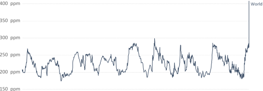
With more than 400ppm, CO2 concentration is highest in the atmosphere since 800.000 years (see Figure 1). Almost all of it can be attributed to human emissions. According to the International Energy Agency (IEA), transport emissions, which primarily involve road, rail, air and marine transportation, account for one quarter of all global CO2 emissions. Freight transport alone consumes around 40% of the energy used in the transportation sector.
Atmospheric CO₂ concentration 
Global average long-term atmospheric concentration of carbon dioxide (CO₂), measured in parts per million (ppm). Long-term trends in CO₂ concentrations can be measured at high-resolution using preserved air samples from ice cores.
100 ppm  50 ppm
0 ppm 
803719 BCE 600000 BCE 400000 BCE 200000 BCE 2018
Source: EPICA Dome C CO₂ record (2015) & NOAA (2018) OurWorldInData.org/co2-and-other-greenhouse-gas-emissions • CC BY
Figure 1: Historic atmospheric CO2 concentration, Source: Our WorldinData.org (https://ourworldindata.org/grapher/co2-concentration-long-term)
To keep temperature rise within a range that averts the worst climate impacts, the IEA suggests that transportation emissions need to peak around 2020 and then decrease fast.
Decarbonization of the transport sector would create a cleaner, healthier and more affordable future for everyone, and it can be done without jeopardizing convenience in mobility, which is expect from modernity. Plus, legislation together with an increasing effort of public and private companies increases the pace towards electrification.
Fuel cells avoid air pollution and global warming generated during burning of fossil fuels. Hydrogen-based fuel cells only generate water as a by-product when the point of use is water. Moreover, fuel cell efficiency outperforms any diesel or gas engine.
While the mobility industry continues to improve the efficiency of traditional combustion engines and reduce vehicle weight by replacing metal via various high performing plastics and composite structure, electrification of the powertrain is an essential part of the solution to the challenge of growing transportation sector emissions because it eliminates tailpipe emissions. Further to strengthen CO2 reduction, fuel cells also reduce air pollution and can further help to reduce sound pollution since fuel cells operate silently compared to internal combustion engines (ICE).
Contrary to battery electric vehicles, fuel cell e-cars have many advantages,see figure 2
− Fast refueling at comparable times to ICE cars
− Driving range is comparable to standard ICE cars
− No heavy battery on board
− Limited weather dependence on the performance of fuel cells vs. lithium batteries (LiBs)
As one of the pillars for the electrification of the mobility segment, fuel cell technologies, especially Proton exchange membrane fuel cell vehicles (PEMFC) has drawn everincreasing attention and it does have a beneficial balance between efficiency and emission. Almost all major OEMs are already investing or planning to invest in commercialization of fuel cell vehicles first targeting lorries and buses, due to the higher relevance of weight and range gains.
Of the various fuel cells technologies, in particular PEMFC is preferred due to its sufficiently low working temperature (80°C to 110°C), a short start up time and ability to run on pure hydrogen and ambient air as the oxidant and comparable re-fueling time to ICEs.
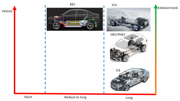
Figure 2: Driving range comparison of different drive trains
Besides all the advantages of PEMFC, it is a delicate device that requires cautious consideration from material selection, design, manufacturing and quality control. Improper material selection for fuel cell construction could result in catastrophic failures. Impurities, such as ion leaching from the material will gradually clog the membrane and lead to life time reduction. Components in the fuel cell system exposed to high humidity and temperature will suffer from material hydrolysis, which will lead to deformation and degradation. This material impact will significantly decrease the fuel cell system performance and jeopardize its efficiency and lifetime.
Proton exchange membrane fuel cell vehicle
As one option towards electrical powertrains, fuel cell changes the way of acquiring and generating electricity to power the vehicle. Contrary to plug-in hybrid electrical vehicles (PHEVs) or full battery driven electrical vehicle (BEVs), which rely partly or entirely on the power of lithium ion batteries, fuel cell vehicles (FCEVs) carry an electrochemical power generation system, which converts hydrogen and oxygen to electricity. Heat and water are the only by-products produced during this process.
An efficient and reliable fuel cell system, which can operate for more than 15.000 hours in commercial vehicles, requires a robust electrochemical conversion process. Components— such as air-intake and filtration, hydrogen supply and recirculation, fuel cell stack, thermal management and the related control system—need to be built for seamless and reliable operation at the early design phase. The complete system layout can be found in Figure 3.
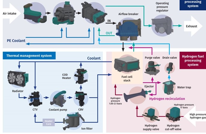
Figure 3: BOP of the fuel cell system
The actual fuel cell stack as the heart of the vehicle consists of hundreds of individual cells and various components manufactured from plastic or metal. Each individual cell is made of a sandwich structure of a bipolar plate and a membrane electrode assembly (MEA), which has two gas dissipation layers (GDL) and a Pt catalyst coated membrane.
The GDL typically consists of a substrate, such as carbon paper and a microporous layer. The catalyst coated membrane is composed of a proton conducting membrane covered with two catalyst layers—the membrane is typically made from per-fluorinated sulfonic acid (PFSA) (see Figure 4).
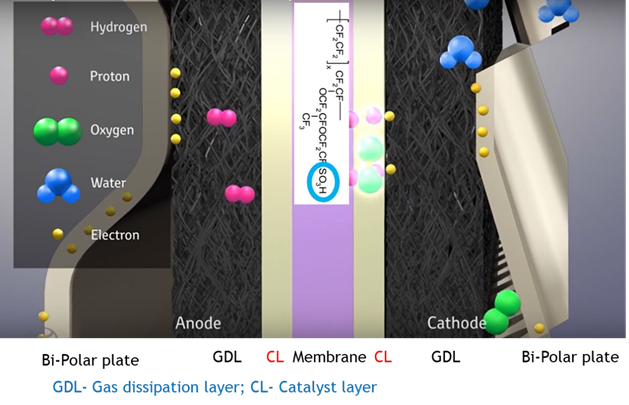
Figure 4: Schematic view of individual cell
The catalyst oxidizes the hydrogen molecules and separates electrons and protons. Protons can then selectively move through the proton exchanging membrane (PEM) from the anode to the cathode, while the electrons can’t pass the membrane and will be forced to travel through an external circuit, leading to a current flow. H2O and heat will be generated during the process as by-products (see Figure 5).
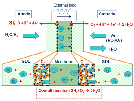
Figure 5: Schematic view of MEA (Source: Effect of impurity on performance of proton exchange membrane fuel cell components by Dr. Kitiya Hongsirikarn)
Potential failure from improper selection of plastic
Various materials, such as metal, rubber and thermoplastic, are being utilized to build a fuel cell system. Engineering plastics are selected due to their easy processability, lighter weight and intrinsic electrical insulation. There is a broad variety of engineering plastics that can be used.
However, to build a fuel cell system for long term reliability, selection of the right material is crucial to ensure the best efficiency and lifetime performance. Figure 6 summarizes the potential failures that can arise through improper selection of engineering materials.
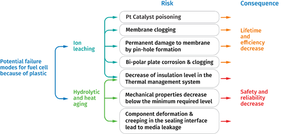 Figure 6: Potential failure modes
Purity matters
Given the fact that a fuel cell is an electro-chemical device, elements that could unintentionally participate into the main reaction process will decrease the fuel cell performance. Impurities, such as ions and toxic gases, could come from the gas (H2 and air) supply loop and thermal management loop, as well as the materials which are used to build the components of the system. Therefore, understanding the advantages and limitations of the material are crucial for the fuel cell system to be a success.
Potential impurities are typically toxic gases, such as H2S, CO and NH3, which are known as the most contaminative gases for fuel cells and the ionic contamination from external pollution or from material corrosion. Impurities of the gas can lead to serious Pt-based catalyst poisoning, which leads to the reduction of the proton production (see Figure 7).
Ionic contaminations from materials, such as Na+, Ca2+, Fe2+, Ma2+,Al3+,Si4+ will lead to severe membrane clogging. The result being a significant decrement of the proton transmission capability and membrane conductivity. Moreover, excessive ion leaching in the cooling loop will decrease the insulation level of the vehicle and also accelerate the corrosion of the metallic bi-polar plate. While manufacturers typically take active steps to reduce the ionic contamination of the supplied gases, DSM as an engineering material supplier additionally contributes to reducing the ionic leaching from the plastic materials used in the system.
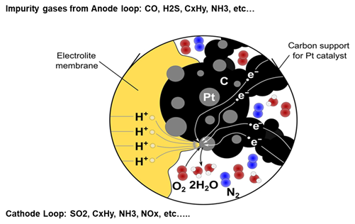
Figure 7 : Catalyst poisoning from external gas contamination (Source: Energy Science & Engineering, Volume: 7, Issue: 6, Pages: 2519-2539, First published: 04 September 2019, DOI 10.1002/ese3.441)
Proton transmission mechanism through the membrane
The molecular structure of a typical PFSA ionomer based membrane is shown in Figure 8. It consists of two regions, the PTFE backbone providing chemical/mechanical/thermal stability, and the hydrophilic perfluoroether side with sulfonic acid(-SO3H) groups involved in the proton transport process.
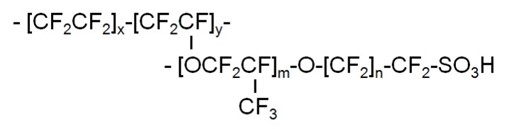
Figure 8: PFSA ionomer
Proton transmission through the membrane mainly involves two mechanisms, which are known as the Grötthuss mechanism and the vehicle or diffusion mechanism (see Figure 9). In general, the vehicle mechanism is slower than the Grötthuss and depends on the diffusion rate. In the Grötthuss mechanism, proton in the form of H+3O is hopping through -SO3H groups to the H2O.
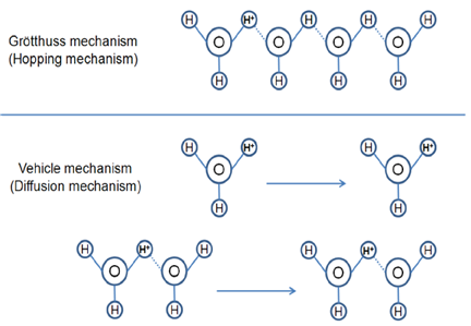
Figure 9 Grötthuss hopping mechanism ( Source: R. Thakkar, H. Patel, U. Chudasama, “A Comparative Study of Proton Transport: Properties of Zirconium Phosphate and Its Metal Exchanged Phases”, Bull. Mater. Sci. 30 (2007) 205-209)
As mentioned in the previous section, cations (Na+, Ca2+, Fe2+, Mg2+,Al3+,Si4+…) all have either higher valence or higher molecular mass. Those cations will compete with protons for the main reaction, and they could form cation-water cluster, such as Na+(H2O)6, Ca2+(H2O)6, Fe2+ (H2O)8… These clusters have a much higher molecular mass and due to the higher valence the affinities to the -SO3H is stronger than protons. Because of this effect, it significantly reduces the membrane conductivity. As such, the proton transmission rate is reduced significantly.
In the worst case, excessive ion leaching could lead to pin-hole formation in the membrane, creating permanent damage. Those types of problems could significantly reduce the fuel cell life time and efficiency. Figure 10 shows the effect of membrane conductivity with the pollution of different cations.
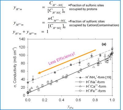
Figure 10 effect of cations(Na+,Ca2+,Fe3+) on the conductivity of a Nafion membrane, 195, (2010),7213-7220
Hydrolytic resistance matters
Since a complete fuel cell system consists of the three main sub-systems—air intake system, hydrogen supply system and thermal management system—components in all three systems have to be robustly connected and sealed at the interfaces to avoid media leakage (see Figure 3).
The fuel cell system works mostly in a temperature range between 70 to 90°C, with almost 100% humidity and mild acidic conditions. While these conditions may look moderate at first glance, they actually are severe enough to strongly deteriorate the material performance—especially for long term mechanical properties, such as creep resistance. Components built with less hydrolytic resistant materials will suffer under such conditions resulting in warpage, deformation and eventually media leakage at the sealing interface.
To enable manufacturers’ best component performance, DSM has developed not only superior engineering materials for fuel cells, but also ensures detailed calculation tools to predict the long term hydrolytic performance under such severe conditions.
Lowest ion leaching from Xytron™ PPS fuel cell platform
Based on a deep understanding of potential fuel cell failure modes caused by engineering materials and targeted to provide a robust material solution for long term reliability of the fuel cell vehicle, DSM has created a technical platform based on Xytron™ PPS with the industry’s lowest ion leaching and highest hydrolytic resistance.
Experiments and research have been done at DSM to compare the ion leaching performance among different polymer options (see Figure 11 and 12).
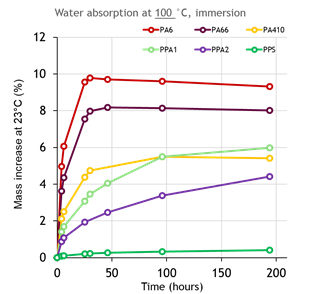
Figure 11: Water absorption of different polymer compounds in 100℃ hot water till equilibrium
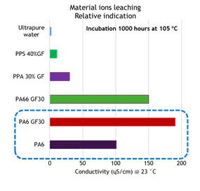
Figure 12: Solution conductivity after 1,000 hours. Deionized water soaking— indication of ion leaching
By comparing the data shown in Figure 11 and Figure 12, it seems that the amount of ion leaching from polymer compounds are in reverse correlation with its moisture absorption. It is well known that due to its molecular structure, polyamides absorb moisture. The level of moisture absorption depends significantly on the density of the amide groups in the molecule and also its level of crystallinity.
In general, short chain aliphatic polyamides absorb more moisture than long chain polyamides or aromatic polyamides (PPAs). However, Figure 12 shows that PA6 and PA66 compound with 30% glass fiber absorbs less moisture, but has higher ion leaching. Based on DSM studies, this relates to glass fiber corrosion and degradation of the interface between glass fibers and polymer.
As all polyamides absorb a certain amount of moisture, it creates more “reaction points” for the moisture(H2O)to corrode glass fibers and degrade the interface chemistry, thus extra ion leaching at these interfaces occurs. Moreover, moisture absorption will decrease the
42nd
11
glass transition temperature Tg of polyamide, which results in “softening” effects of the polymer, resulting in dimensional instability and a decrease of the high temperature creep resistance. As a contrast, Polyphenylene sulfide (PPS) barely absorb moisture and its semi crystalline material with non-polar molecular structure enables excellent chemical resistance and low ion leaching, as well as excellent dimensional stability.
Although glass fiber reinforced PPS compounds perform much better in ion leaching than polyamides, DSM has achieved a further significant improvement by optimizing the interface chemistry between glass fibers and the PPS polymer. By strengthen the bonding of the interface, DSM is able to minimize the ion leaching far below alternative PPS compounds.
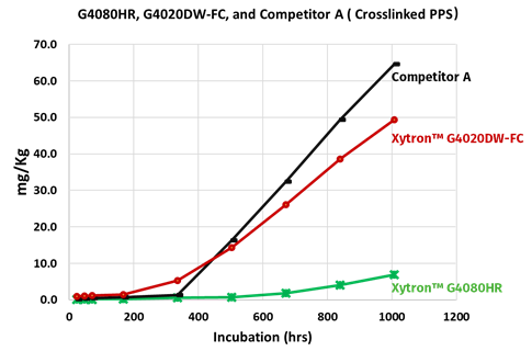
Figure 13: Comparison of absolute ion (sum of all ions) leaching after 90℃ DI water incubation
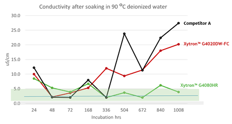
Figure 14 Solution conductivity after 90℃ DI water incubation
Figure 13 and 14 show the results of ion leaching and solution conductivity after full exposure to deionized water at 90°C. Xytron™ G4080HR is one of the grades from the Xytron™ PPS fuel cell platform. Xytron™ G4020DW-FC is the standard Xytron™ PPS grade and the competition grade is a cross-linked PPS compound. The three grades are all 40% glass fiber reinforced PPS compounds.
In order to simulate the real fuel cell system operation in the experiments, the DI water during the specimen incubation was completely refreshed at each data point to avoid local ion concentration equilibrium since in the real application the water does not standstill. In addition to the testing, a six week long continuous incubation was done, as well for reference. This shows the same trend—Xytron™ G4080HR with the dedicated interface technology shows the lowest ion leaching and solution conductivity. The other standard grades without such interface technology show a similar higher amount of ion leaching and solution conductivity.
XytronTM PPS fuel cell platform offers the highest hydrolic resistance
A high hydrolytic resistance of the engineering materials is crucial to ensure good mechanical properties of fuel cell components under environmental impact. Figure 15 and 16 compare the mechanical hydrolytic resistance of different polymers.
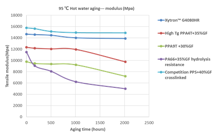
Figure 15: Comparison of 95℃ hot water aging of polymer compounds-modulus
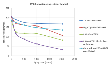
Figure 16: Comparison of 95℃ hot water aging of polymer compounds-strength
42nd
13
In general, PPS shows a much better long term mechanical retention compared to PAs. Yet, a clear difference can be seen within the PPS group, especially in tensile strength. The specially improved Xytron™ G4080HR material results in the highest mechanical retention. The higher moisture absorption of PAs shift Tg lower and as a result leads to a softening of the material (see Figure 17). After long term exposure to hot water, H2O breaks down the amide group and hydrolyzes the plastic material resulting in severe reduction of its molecular weight.
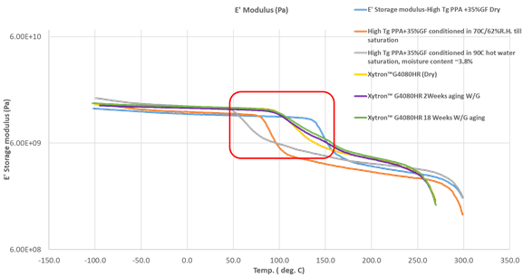
Figure 17: Comparison of DMTA—Storage modulus (E‘ modulus) between high Tg PPA and PPS in different status (dry as molded, after moisture absorption till saturation and after hydrolytic aging)
Polyamides, even those with the high glass transition temperature (Tg), will suffer of this softening behavior. Xytron™ G4080HR with 40%GF is an extremely stable material, even aging at 135°C for 3000 hours, does not lead to a Tg shift. High Tg PPA compounds with 35%GF take less than 250 hours soaked in 90°C hot water until they reach moisture absorption equilibrium with moisture content of ~ 3.8%.
Such PPA compounds is typically known as the most hydrolytic resistance and highest Tg polyamides in the industry, but still PPA encounters a Tg shift from 149°C down to 68°C. As Tg determines the molecule mobility for the polymer, below Tg the polymer molecule is frozen and does not have mobility, therefore it is rigid with strong creep resistance. Above Tg, the molecules get mobile and are able to be twisted and moved. This “softening” effect due to moisture absorption leads to significant reduction in dimensional stability and creep resistance.
A working condition of 90°C at 100% humidity is very typical for a fuel cell system. Polyamides even with the highest Tg will be fully moisture saturated at such conditions, already after the first few hundred operation hours. Therefore, hydrolytic degradation of the polyamide molecule occurs.
If fuel cell parts are manufactured out of polyamides, they would suffer expansion in dimension. The mechanical properties, such as creep resistance, mechanical strength and Modulus would drop, leading to component deformation. Due to the induced creep and deformation at sealing interfaces the fuel cell system faces a high failure risk. Figure 18 summarizes the mechanical retention and ion leaching performance vs. long term hydrolytic aging.
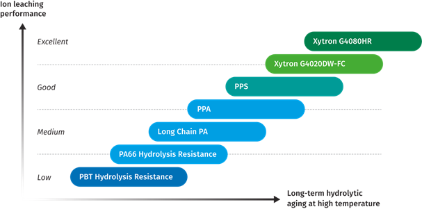
Figure 18: Material ranking of hydrolytic resistance and ion leaching performance
DSM has systematically studied the hydrolytic aging mechanism with different polymers and acquired more than 10,000 hours measurement data in high temperature hydrolytic solution. DSM is not only able to provide the comparison of hydrolytic performance among polymer compounds, it can also predict mechanical retention in either water or water/glycol systems up to 30,000 hours. Figure 19 shows the modelling of the tensile strength up to 30,000 hours based on Xytron™ PPS G4080HR with good prediction accuracy.
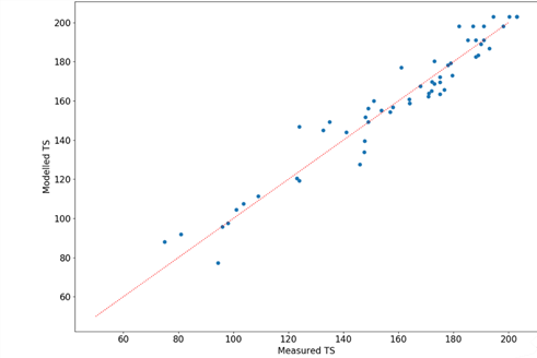
Figure 19: Comparison between tensile modulus modelling and measurement data based on Xytron™
PPS G4080HR shows good alignment between model prediction and actual measurement data
42nd
15
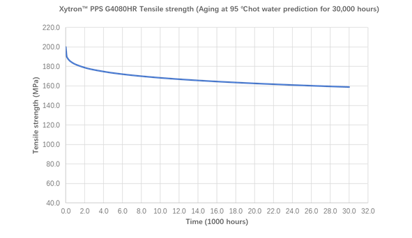
Figure 20: Prediction of tensile strength retention in the 95℃ Xytron™ PPS G4080HR up to 30,000 hours
Figure 20 shows 30,000 hours tensile strength prediction results of Xytron™ PPS G4080HR in 95°C hot water. Its extremely stable mechanical retention makes it to be the best hydrolytic resistant material in the industry, outperforming all PPAs and significantly outperforming other standard PPS, which provides a sufficient safety margin for long term reliability of the components.
Summary
Advanced technologies are radically transforming the powertrain of transport for humans. PEMFC fuel cells provide a new possibility of zero emissions and the lowest environmental impact, which will contribute to a carbon neutral society.
The application of PEMFC fuel cells is not limited in automotive, but can be applied to forklift, airplanes, boats and drones. It is a technology platform with vast possibilities. In many countries, due to the lack of investing in infrastructure for both hydrogen production and hydrogen stations, the first attempt and deployment of PEMFC in automotive remains in the commercial transport space, with one exception being Japan. In Japan there is an ambitious government incentive plan to build a hydrogen society, in which Japanese OEMS are taking leadership positions in.
As mentioned, the core technologies of the fuel cell for different transports are almost the same, so it is important to build the fuel cell system with the highest reliability to cover most of transports. For example, commercial vehicles typically require a lifetime over 15,000 hours. So selecting material with the first time right would avoid potential failures of fuel cell systems, and ensure a competitive advantage.
With comprehensive studies DSM research has done over the years, we are confident to provide material options to fit the requirements of different fuel cell components. Among all of the potential engineering materials, PPS has been identified as the most suitable polymer for fuel cell systems, due to its intrinsically excellent properties, such as chemical resistance, hydrolytic resistance, excellent dimension stability and low ion leaching.
With DSM innovative interface technology, we are able to create a Xytron™ PPS fuel cell platform with:
-
The lowest ion leaching of its kind to ensure the highest fuel cell efficiency and life time;
-
The best strength and toughness retention in the hydrolytic environment (among all engineering plastics)—it outperforms other PPS and PPAs, enabling maximum design flexibility for engineers
-
The best dimensional stability, fatigue and creep resistance of its kind, even after aging, ensuring high system reliability for as long as its service time
-
The best welding line strength before and after hydrolytic and heat aging to ensure the highest mechanical reliability
Currently, with the Xytron™ PPS fuel cell platform, DSM is able to offer three grades:
-
Xytron™ PPS G4080HR (standard)
-
Xytron™ PPS + 30%GF+ Impact modifier for better toughness
-
Xytron™ PPS + 40% GF + Impact modifier for the balance between strength and toughness
Part of DSM’s strategic direction is to focus on and invest in PEMFCs. We are committed to cooperate with industrial partners to move this promising technology forward and create a bright living with our bright science.
To learn more about DSM PPS
XytronTM grades, you can contact the individuals below or visit our websites:
-
Yu Bin- Global technical experts E mobility(HEV, PHEV, BEV, Fuel cell) Bin.yu@dsm.com
-
Tamim sidiki- Global marketing director automotive; Sidiki.tamim@dsm.com
-
Qiu Jun- Application specialist & Chemical scientist Europe;
Qiu.jun@dsm.com
-
Pot Abel- Application specialist in Europe
Abel.pot@dsm.com


Homepage
DSM.com/engineering-materials
42nd
17
Product and technical data PlasticsFinder.com
 欢迎关注川大高分子校友会公众号,查看通讯录
 川大高分子校友会网址:https://www.scupse.com/