
Miniaturization and Electronics Integration Special
Category: Miniaturization
Sub-category: Nylons
Industry: Electrical & Electronics
The Authors
Patrick Duis is Innovation Manager E&E at DSM Engineering Plastics B.V., Geleen, The Netherlands
Yu Bin is Manager ADTS (Application Development & Technical Support) and Director R&D at DSM’s
Performance Materials Research Center in Shanghai, China
Dr. Gerard Haagh is Senior Scientist Injection Molding at DSM in Geleen
Managing the Smallest Melt Volumes
Influencing Melt Flow when Molding Thin-Walled Electronic Components in HighPerformance Polyamide Resins
[Abstract:]
Thermoplastic materials must prove their fit in ever smaller and powerful electronic components. A more detailed investigation was carried out focusing on the melt compression experienced when USB-C connectors are injection molded in polyamide resins, as it has shown to have a significant effect on melt flow and is an important factor in thin-wall component molding.
[Introduction:]
Electronic components such as for connectors must become ever smaller, thinner and powerful, which places increasingly higher demands on the key properties of thermoplastic materials. The development of these components requires a solid understanding of the parameters influencing the injection molding process. An important and often neglected role in this process is attributed to melt compression which has a critical effect on the melt flow rate particularly in the case of extremely thin-walled components.
The criteria to be met by thermoplastics for use in thin-walled electronic components are many and often interdependent. They include high flow; high strength; compatibility with high-temperature lead-free soldering operations; high flame retardancy (often as high as UL94 V-0 at 0.2 mm), very good glow wire ignition resistance, high pin retention strength, and colorability.
Moreover, the wall thicknesses of components for personal electronics have come down by an average of around 12% each year. In some cases, processors need to produce parts with walls as thin as 0.15 mm. With this progression in miniaturization, certain phenomena that may be negligible in the production of larger parts have taken on critical importance. One of these phenomena is melt compression.
Effects of Melt Compression
There is very little information in literature to indicate or enable calculations of how much compression occurs when small parts are injection molded. This is rather surprising, since the implications of melt compression on melt flow and thus on the successful injection molding of very thin-walled parts are severe
(Fig. 1).
New USB-C connectors, for example, must carry more power in a very compact size format, including pin pitches down to 0.5 mm (vs. 2.0 mm in USB Type A connectors) and insulation wall thicknesses of only 0.12 mm (vs. 1.84 mm). The schematics in Figures 2 and 3 illustrate the manufacturing steps for USB-C connectors and give an idea of how difficult it is to successfully and repeatably mold such thin-walled components, particularly if they are meant to meet the required mechanical and – critically – electrical properties.
An understanding of melt compression will be crucial to the successful production of such components. At DSM Engineering Plastics BV in Geleen, The Netherlands, researchers have analyzed the effect of melt compression on mold filling. They equipped the cavity of a thin-wall strip mold with two surface-mounted piezoelectric pressure transducers to measure the passing melt flow front. A 1,800 ton hydraulic injection molding machine with a 15 mm screw was used to mold the strips, applying screw injection rates between 20 and 40 cm3/s. Trials were carried out using various different materials, including polypropylene (PP) and several types of polyamide (PA) resins.
The tests elicited some surprising results. With an unfilled, low-viscosity PP processed at a set screw injection rate of 40 cm3/s, the actual mold filling rate was less than 2 cm3/s. Subsequent tests were carried out to measure the actual filling rate in the commercial molding process of a 32-cavity mold for a thinwalled connector, using an unfilled flame retardant PA6 material. While noting that the actual screw injection rate was lower than the set rate (due to the response characteristics of the (hydraulic machine), the researchers again found a major discrepancy in a ratio of 5:1 between the screw injection and mold filling rates.
The researchers created a mathematical model to describe melt compression, which they then validated in molding trials using DSM’s high performance Stanyl PA46. The polymer is used in thin-wall connector applications requiring very good thermal characteristics, such as for reflow soldering. Agreement between the cavity filling rate calculated from the model and the actual filling rate was very close.
Several options were then considered for reducing the melt compression effect in conventional injection molding processes: First, the compressibility of the melt could be decreased by the addition of fillers, which would however have negative effects on flow and finished part properties. Second, the melt viscosity could be reduced, but at the risk of inferior mechanical properties. Further investigation included reducing the melt volume in the machine and in the (hot) runner system and/or the number of mold cavities to be filled simultaneously.
DSM has gained substantial experience in this regard during development of the latest generation of connectors for Double Data Rate Synchronous Dynamic Random Access Memory (DDR SDRAM), DDR4, SMT terminal blocks as well as USB-C connectors. The bottom line is the melt compression effect on the mold filling rate can be minimized, if the mass of melt between the screw tip and the cavity gate(s) is reduced. This may appear obvious, but is a fundamental rule that is frequently not applied in practice in the authors’ experience.
Reducing the Melt Cushion
The melt cushion or the amount of material in the barrel ahead of the screw at the switchover point is typically as small as possible for achieving stable process conditions on a small machine, e.g. equipped with an 18-20 mm screw. The bigger the cushion, the higher the melt compression effect. The equation shown in Figure 4 indicates the importance of melt compression. In tests using a small injection molding machine fitted with a single-cavity mold for the production of a simple test bar, the flow rate based on a screw injection speed set to approximately 40 cm3/s went down to as low as 2 cm3/s by the time the melt reached the cavity (Fig. 5).
This means that there is a compelling need to minimize the melt volume ahead of the screw in the barrel, in the (hot) runner system and perhaps also in the sprue bushing. This can be achieved, for instance, by using a smaller barrel, a smaller nozzle, and a shorter (hot) runner. In addition, it clearly helps to set the switchover point to where the screw is as far forward as possible. The lower the melt volume in front of the screw, the higher will be the melt flow rate in the cavity.
Practice showed that a reduction of the melt volume provides considerable assistance in increasing the mold filling speed. In some cases, it was even possible to eliminate the problem of short shots in thin-wall application, altogether. Figure 6 illustrates the potential influence on the actual mold filling rate when reducing the flow channel volume between the front of the screw and the cavity gates. Trials were carried out using different PA46 compounds and an unfilled polypropylene resin. The test mold was designed for delivering flow bars with a wall thickness of 0.2 mm.
Machine type (electric/hydraulic) and configuration can also have a large effect on flow behavior. Electric machines stand out, among other things, for their excellent dynamics in terms of screw acceleration and top speed. In thin-wall molding tests carried out by DSM together with several machine suppliers, the cavity flow rates achievable with an electrical machine were three times as high as those on a comparable hydraulic machine. Test material was a high-flow grade of PA46 with 40% glass fibers and a flame retardant, for molding a test bar with 0.2 mm wall thickness.
Next to melt compression, there are a number of further fundamental considerations to be taken in account also on the material side when molding thin-walled electronic components. These include appropriate melt viscosity for high flowability, such as offered by PA46 grades of the Stanyl HF series. In contrast, the incorporation of flow-enhancing processing aids frequently has a negative effect on mechanical properties and on long-term resistance to thermal ageing. Another requirement is high flame retardancy, preferably relying on a halogen-free flame retardant, to provide certified UL94 V-0 ratings at the smallest wall-thicknesses. Stanyl ForTii PA4T from DSM has an ideal fit in this demanding application segment.
In addition, materials used for thin-walled electronic components must also exhibit high tracking resistance.
DSM’s PA46 and PA4T materials approved for these applications by several manufacturers both have a Comparative Tracking Index (CTI) of Performance Level Category 0 (> 600 V), i.e. higher than many competitive materials, including liquid crystal polymers, which are normally rated just in PLC 2 (< 400 V). Further important requirements are high heat resistance for lead-free reflow soldering processes as well as compatibility with ultrasonic welding techniques.
Moreover, connectors must often meet durability specifications of up to 10,000 mating/unmating cycles, requiring materials that are also capable of providing long-term wear resistance. Last but not least, DSM polyamide resins are available in a broad selection of colors, and specifiers can make use of the company’s color matching service to obtain exactly the color they want.
Conclusion
The ongoing trend towards miniaturization in electronics, which shows no sign of coming to an end, entails new challenges for the suppliers and processors of thermoplastics used in such components. Work is continuing to gain a better understanding of the interaction of various key end-use and processing properties of high performance materials in order to ensure that processors will be able to meet the increasing demands of electronics manufacturers. Research of important phenomena observed during thinwall molding, especially melt compression, provides valuable insight for processors to ensure high-quality production.
[Figures & Captions:]
[Lead Photo:]

Thin-walled DDR4 connectors molded in halogen-free flame retardant Stanyl ForTii PA4T
(All illustration by courtesy of DSM)
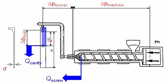
Figure 1 Schematic representation of essential pressures and flow rates in thin-wall injection molding
(Qscrew = set screw injection rate, Qcavity = melt flow rate in mold cavity, pmachine = melt compression in plasticizing barrel, prunner = melt compression in (hot) runner system, pmold = melt compression in mold cavity, L = flow length in mold)
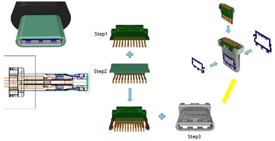
Figure 2 Schematic illustration of individual USB-C plug manufacturing steps. Core criteria include precise and repeatable filling of parts at wall thicknesses of 0.12 mm as well as heat deflection temperature and dimensional stability for reflow soldering.
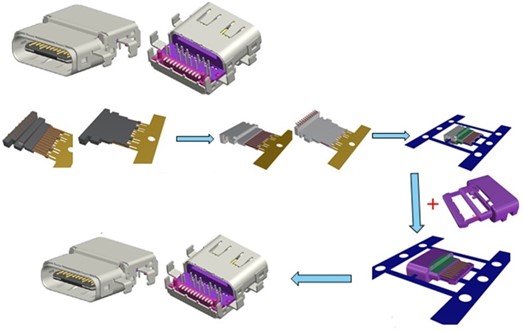
Figure 3 Schematic illustration of USB-C receptacle manufacturing steps. Important requirements are high flowability in a narrow processing window, high-precision mold design and suitable equipment selection.
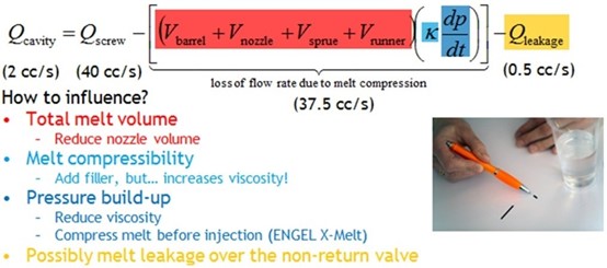
Figure 4 Simplified calculation model for assessing the flow loss due to melt compression
(Vcavity = cavity filling rate, Qscrew = set screw injection rate, Vbarrel = melt volume in barrel in front of screw, Vnozzle = melt volume in machine nozzle, Vsprue = melt volume in sprue bushing, Vrunner = melt volume in (hot)runner system, Qleakage = melt flow rate loss due to leakage)
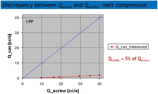
Figure 5 Effect of melt compression when molding flow bars in polypropylene at controlled injection rate (Q_screw). The blue line indicates the ideal flow rate (Q_cavity = Q_screw). The red curve shows the measured actual values (Q_cavity = 5% of Q_screw).
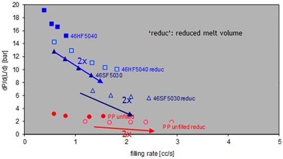
Figure 6 Higher filling rates and lower flow resistance. The featured polyamide resins benefit from reducing the melt volume (here by 25%) to minimize melt compression
 欢迎关注川大高分子校友会公众号,查看通讯录
 川大高分子校友会网址:https://www.scupse.com/